MRI(Magnetic resonance imaging)

SONY DSC

Introduction:

Magnetic resonance imaging (MRI), nuclear magnetic resonance imaging (NMRI), or magnetic resonance tomography (MRT) is a medical imaging technique used in radiology to investigate the anatomy and function of the body in both health and disease. MRI scanners use strong magnetic fields and radio waves to form images of the body. The technique is widely used in hospitals for medical diagnosis, staging of disease and for follow-up without exposure to ionizing radiation.

Magnetic resonance imaging (MRI) is a test that uses a magnetic field and pulses of radio wave energy to make pictures of organs and structures inside the body. In many cases MRI gives different information about structures in the body than can be seen with an X-ray, ultrasound, or computed tomography (CT) scan. MRI also may show problems that cannot be seen with other imaging methods.

MRI

For an MRI test, the area of the body being studied is placed inside a special machine that contains a strong magnet. Pictures from an MRI scan are digital images that can be saved and stored on a computer for more study. The images also can be reviewed remotely, such as in a clinic or an operating room. In some cases, contrast material may be used during the MRI scan to show certain structures more clearly.


Neuroimaging:

download
MRI image of white matter tracts.
MRI is the investigative tool of choice for neurological cancers as it is more sensitive than CT for small tumors and offers better visualization of the posterior fossa. The contrast provided between grey and white matter make it the optimal choice for many conditions of the central nervous system including demyelinating diseases, dementia, cerebrovascular disease, infectious diseases and epilepsy.

Liver and gastrointestinal MRI:

PAPVR (1)
Hepatobiliary MR is used to detect and characterize lesions of the liver, pancreas and bile ducts. Focal or diffuse disorders of the liver may be evaluated using diffusion-weighted, opposed-phase imaging and dynamic contrast enhancement sequences. Extracellular contrast agents are widely used in liver MRI and newer hepatobiliary contrast agents also provide the opportunity to perform functional biliary imaging. Anatomical imaging of the bile ducts is achieved by using a heavily T2-weighted sequence in magnetic resonance cholangiopancreatography (MRCP). Functional imaging of the pancreas is performed following administration of secretin. MR enterography provides non-invasive assessment of inflammatory bowel disease and small bowel tumors. MR-colonography can play a role in the detection of large polyps in patients at increased risk of colorectal cancer.

Function of MRI:

images (6)

Functional MRI (fMRI) is used to understand how different parts of the brain respond to external stimuli. Blood oxygenation level dependent (BOLD) fMRI measures the hemodynamic response to transient neural activity resulting from a change in the ratio of oxyhemoglobin and deoxyhemoglobin. Statistical methods are used to construct a 3D parametric map of the brain indicating those regions of the cortex which demonstrate a significant change in activity in response to the task. FMRI has applications in behavioral and cognitive research as well as in planning neurosurgery of eloquent brain areas.

images

How MRI works:

To perform a study the patient is positioned within an MRI scanner which forms a strong magnetic field around the area to be imaged. Most medical applications rely on detecting a radio frequency signal emitted by excited hydrogen atoms in the body (present in any tissue containing water molecules) using energy from an oscillating magnetic field applied at the appropriate resonant frequency. The orientation of the image is controlled by varying the main magnetic field using gradient coils. As these coils are rapidly switched on and off they create the characteristic repetitive noises of an MRI scan. The contrast between different tissues is determined by rate at which excited atoms return to the equilibrium state. Exogenous contrast agents may be given intravenously, orally or intra-articularly.

Effects of TR and TE on MR signal.

Magnetic resonance angiography:

Magnetic resonance angiography (MRA) generates pictures of the arteries to evaluate them for stenosis (abnormal narrowing) or aneurysms (vessel wall dilatations, at risk of rupture). MRA is often used to evaluate the arteries of the neck and brain, the thoracic and abdominal aorta, the renal arteries, and the legs (called a “run-off”). A variety of techniques can be used to generate the pictures, such as administration of a paramagnetic contrast agent (gadolinium) or using a technique known as “flow-related enhancement” (e.g., 2D and 3D time-of-flight sequences), where most of the signal on an image is due to blood that recently moved into that plane, see also FLASH MRI.


images (4)

Techniques involving phase accumulation (known as phase contrast angiography) can also be used to generate flow velocity maps easily and accurately. Magnetic resonance venography (MRV) is a similar procedure that is used to image veins. In this method, the tissue is now excited inferiorly, while the signal is gathered in the plane immediately superior to the excitation plane—thus imaging the venous blood that recently moved from the excited plane

Susceptibility weighted imaging (SWI):

Susceptibility weighted imaging (SWI), is a new type of contrast in MRI different from spin density, T1, or T2 imaging. This method exploits the susceptibility differences between tissues and uses a fully velocity compensated, three dimensional, RF spoiled, high-resolution, 3D gradient echo scan.

mri_brain_0 This special data acquisition and image processing produces an enhanced contrast magnitude image very sensitive to venous blood, hemorrhage and iron storage. It is used to enhance the detection and diagnosis of tumors, vascular and neurovascular diseases (stroke and hemorrhage, multiple sclerosis, Alzheimer’s), and also detects traumatic brain injuries that may not be diagnosed using other methods.


Cloud Computing

Cloud-Computing-from-any-device

Definition:

Cloud computing is a phrase used to describe a variety of computing concepts that involve a large number of computers connected through a real-time communication network such as the Internet. In science, cloud computing is a synonym for distributed computing over a network, and means the ability to run a program or application on many connected computers at the same time.

download (1)

The phrase also more commonly refers to network-based services, which appear to be provided by real server hardware, and are in fact served up by virtual hardware, simulated by software running on one or more real machines. Such virtual servers do not physically exist and can therefore be moved around and scaled up or down on the fly without affecting the end user, somewhat like a cloud.

Advantages:

Cloud computing relies on sharing of resources to achieve coherence and economies of scale, similar to a utility (like the electricity grid) over a network. At the foundation of cloud computing is the broader concept of converged infrastructure and shared services.
The cloud also focuses on maximizing the effectiveness of the shared resources. Cloud resources are usually not only shared by multiple users but are also dynamically reallocated per demand.

images (2)

This can work for allocating resources to users. For example, a cloud computer facility that serves European users during European business hours with a specific application (e.g., email) may reallocate the same resources to serve North American users during North America’s business hours with a different application (e.g., a web server). This approach should maximize the use of computing powers thus reducing environmental damage as well since less power, air conditioning, rackspace, etc. is required for a variety of functions.
The term “moving to cloud” also refers to an organization moving away from a traditional CAPEX model (buy the dedicated hardware and depreciate it over a period of time) to the OPEX model (use a shared cloud infrastructure and pay as one uses it).
Proponents claim that cloud computing allows companies to avoid upfront infrastructure costs, and focus on projects that differentiate their businesses instead of infrastructure.Proponents also claim that cloud computing allows enterprises to get their applications up and running faster, with improved manageability and less maintenance, and enables IT to more rapidly adjust resources to meet fluctuating and unpredictable business demand.

Hosted services:

cloud_models

The term “cloud computing” is mostly used to sell hosted services in the sense of application service provisioning that run client server software at a remote location. Such services are given popular acronyms like ‘SaaS’ (software as a service), ‘PaaS’ (platform as a service), ‘IaaS’ (infrastructure as a service), ‘HaaS’ (hardware as a service) and finally ‘EaaS’ (everything as a service). End users access cloud-based applications through a web browser, thin client or mobile app while the business software and user’s data are stored on servers at a remote location. Examples include Amazon web services and Google App engine which allocate space for a user to deploy and manage software “in the cloud”.

Growth and popularity:

www.cloudcomputingsite.blogspot.in
The development of the Internet from being document centric via semantic data towards more and more services was described as “Dynamic Web”. This contribution focused in particular in the need for better meta-data able to describe not only implementation details but also conceptual details of model-based applications.

images
The present availability of high-capacity networks, low-cost computers and storage devices as well as the widespread adoption of hardware virtualization, service-oriented architecture, autonomic, and utility computing have led to a growth in cloud computing.

Characteristics:

Cloud computing exhibits the following key characteristics:

  • Agility: improves with users’ ability to re-provision technological infrastructure resources.
  • Application programming interface (API) accessibility to software that enables machines to interact with cloud software in the same way that a traditional user interface (e.g., a computer desktop) facilitates interaction between humans and computers. Cloud computing systems typically use Representational State Transfer (REST)-based APIs.

Figure-2-Sample-Cloud-Decision-Framework

  • Cost: cloud providers claim that computing costs reduce. A public-cloud delivery model converts capital expenditure to operational expenditure.This purportedly lowers barriers to entry, as infrastructure is typically provided by a third-party and does not need to be purchased for one-time or infrequent intensive computing tasks. Pricing on a utility computing basis is fine-grained, with usage-based options and fewer IT skills are required for implementation (in-house). The e-FISCAL project’s state-of-the-art repository contains several articles looking into cost aspects in more detail, most of them concluding that costs savings depend on the type of activities supported and the type of infrastructure available in-house.

images (5)


  • Device and location independence enable users to access systems using a web browser regardless of their location or what device they use (e.g., PC, mobile phone). As infrastructure is off-site (typically provided by a third-party) and accessed via the Internet, users can connect from anywhere.
  • Virtualization technology allows sharing of servers and storage devices and increased utilization. Applications can be easily migrated from one physical server to another.
  • Multitenancy enables sharing of resources and costs across a large pool of users thus allowing for:Reliability improves with the use of multiple redundant sites, which makes well-designed cloud computing suitable for business continuity and disaster recovery.
    Scalability and elasticity via dynamic (“on-demand”) provisioning of resources on a fine-grained, self-service basis near real-time(Note, the VM startup time varies by VM type, location, os and cloud providers), without users having to engineer for peak loads.
  • images (3)centralization of infrastructure in locations with lower costs (such as real estate, electricity, etc.)
    • peak-load capacity increases (users need not engineer for highest possible load-levels)
    • utilisation and efficiency improvements for systems that are often only 10–20% utilised.

Security:

download (3)

As cloud computing is achieving increased popularity, concerns are being voiced about the security issues introduced through adoption of this new model. The effectiveness and efficiency of traditional protection mechanisms are being reconsidered as the characteristics of this innovative deployment model can differ widely from those of traditional architectures. An alternative perspective on the topic of cloud security is that this is but another, although quite broad, case of “applied security” and that similar security principles that apply in shared multi-user mainframe security models apply with cloud security.

download (2)
The relative security of cloud computing services is a contentious issue that may be delaying its adoption.Physical control of the Private Cloud equipment is more secure than having the equipment off site and under someone else’s control. Physical control and the ability to visually inspect data links and access ports is required in order to ensure data links are not compromised. Issues barring the adoption of cloud computing are due in large part to the private and public sectors’ unease surrounding the external management of security-based services.

Leap Motion

leap-motion-review

Definition:

Leap Motion, Inc. is an American company that manufactures and markets a computer hardware sensor device that supports hand and finger motions as input, analogous to a mouse, but requiring no hand contact or touching.

Leap Motion is one of the coolest gadgets that anybody has ever seen in the recent times. It opens door for a wide range of possibilities and has quickly gained momentum over the past year. For those who are still wondering what Leap Motion is, it’s a small sensor which supports hand and finger gestures as input to any computer.

Leap Controller
Leap Controller

Leap Motion, a start up with the ambitious goal of convincing people to control a computer with motion gestures such as the turn of the hand or move of a finger, has taken $30 million in new funding as it prepares to start selling its product by March.

History:

Founded in 2010 as OcuSpec, the company raised a $1.3M seed financing round in June 2011 with investments from venture capital firms Andreessen Horowitz and Founders Fund, SOS ventures as well as several angel investors.[1] In May 2012, Leap Motion announced a $12.75M Series A funding round led by Highland Capital Partners. In January 2013, Leap Motion announced a further series B round of funding for $30M. After operating in quiet since 2010, Leap Motion publicly announced its first product, originally called The Leap, on May 21, 2012. The device started full-scale shipping in July 2013.

Hardware, Technology and Usage:

Leap-Motion-Sensor
Anybody who saw the Leap Motion’s official video, eventually wanted to use one. The device being priced $80, does not burn a hole in your pocket and is considered as an excellent buy for pure entertainment purpose. The device is just an inch wide, less than an inch thick and one would definitely be astonished by its size. There’s a tiny LED status indicator at its front and the device seamlessly connects with a USB port. Leap Motion uses a set of infra red sensors and cameras to detect hand gestures. Also, it can track all your 10 fingers with accuracy as much as hundredth of a millimeter. The powerful hardware when coupled with its software offers great functionality. Leap Motion is easy to set up with your laptop or desktop computer. All you have to is to plug in the Leap Motion to your computer’s USB drive, download a piece of software for your Mac/Windows computer, follow a couple of steps, calibrate the device if necessary and bing,you’re done! Place your hands above the controller and start using Leap Motion.

Software and ecosystem:

download (7)
The Leap Motion’s software is named Airspace and it comes with its own App Store, where you can download apps and software which are specifically designed to work with the Leap Motion controller. Applications range from simple ones like Angry Birds to more complex ones like Photoshop. Yeah, you read it right, you can use your Leap Motion controller to work with your Photoshop projects. The software has an intuitive user interface and offers easy movements and finger based gestures. The Leap motion’s interaction space is split into two zones; the hover zone and the touch zone. The hover zone is used for aiming/moving and the touch zone is used for creating touch based events on the screen.

Controller:

Leap-motion-evolution

The controller will launch in the stores at the end of Q1 and pre-orders will start on Bestbuy.com in February. I spoke to Leap President and COO Andy Miller about the launch and he reassured me that the pre-orders that anxious folks had placed on Leap’s own site over the past few months would be getting fulfilled first.

The Leap Motion Controller is a small unit the size of a Pez dispenser that packs in a couple of cameras, and a software program that does the magic. The result is a pinpoint-accurate 3D controller that allows you to manipulate software apps or your computer’s web browser by waving your fingers in mid air.

Technology:

images

The Leap Motion controller is a small USB peripheral device which is designed to be placed on a physical desktop, facing upward. Using two monochromatic IR cameras and three infrared LEDs, the device observes a roughly hemispherical area, to a distance of about 1 meter (3 feet). The LEDs generate a 3D pattern of dots of IR light and the cameras generate almost 300 frames per second of reflected data, which is then sent through a USB cable to the host computer, where it is analyzed by the Leap Motion controller software using “complex math” in a way that has not been disclosed by the company, in some way synthesizing 3D position data by comparing the 2D frames generated by the two cameras.

tumblr_inline_muv5oohXGY1s31xll
The smaller observation area and higher resolution of the device differentiates the product from the Kinect, which is more suitable for whole-body tracking in a space the size of a living room. In a demonstration to CNET, The Leap was shown to perform tasks such as navigating a website, using pinch-to-zoom gestures on maps, high-precision drawing, and manipulating complex 3D data visualizations. Leap Motion CEO Michael Buckwald told CNET:
Leap Motion initially distributed thousands of units to developers who are interested in creating applications for the device. The Leap Motion controller was first shipped in July, 2013.

Airspace:

Leap Motion has an app store called Airspace where it sells apps made by developers. In November 2013, the LA Times reported that Airspace had reached 150 apps.

And it’s that demo-friendly nature that makes Best Buy a good partnership for Leap. Far from being a niche device for people to ‘play’ with, Leap wants the controller to be everywhere. It’s already struck a deal with Asus to bundle the controller with a new laptop and it has a sliver-thin version that will be embedded into the actual chassis of hardware soon.


Li-Fi(Light Fidelity)

Introduction:

download (5)download (4)download (6)

Li-Fi, or light fidelity, refers to 5G visible light communication systems using light from light-emitting diodes (LEDs) as a medium to deliver networked, mobile, high-speed communication in a similar manner as Wi-Fi. Li-Fi could lead to the Internet of Things, which is everything electronic being connected to the internet, with the LED lights on the electronics being used as internet access points. The Li-Fi market is projected to have a compound annual growth rate of 82% from 2013 to 2018 and to be worth over $6 billion per year by 2018.

download (3)

History:

Prof._Harald_Haas

Professor Harald Haas, from the University of Edinburgh in the UK, is widely recognised as the original founder of Li-Fi. He coined the term Li-Fi and is Chair of Mobile Communications at the University of Edinburgh and co-founder of pureLiFi.
The general term visible light communication (VLC), includes any use of the visible light portion of the electromagnetic spectrum to transmit information. The D-Light project at Edinburgh’s Institute for Digital Communications was funded from January 2010 to January 2012.Haas promoted this technology in his 2011 TED Global talk and helped start a company to market it. PureLiFi, formerly pureVLC, is an original equipment manufacturer (OEM) firm set up to commercialize Li-Fi products for integration with existing LED-lighting systems.

VLC(Visible light communications):

Visible light communications (VLC) signals work by switching bulbs on and off within nanoseconds,which is too quickly to be noticed by the human eye. Although Li-Fi bulbs would have to be kept on to transmit data, the bulbs could be dimmed to the point that they were not visible to humans and yet still functional. The light waves cannot penetrate walls which makes a much shorter range, though more secure from hacking, relative to Wi-Fi.Direct line of sight isn’t necessary for Li-Fi to transmit signal and light reflected off of the walls can achieve 70 Mbps.

download (2)

Construction:

images (1)

The LIFI™ product consists of 4 primary sub-assemblies:

• Bulb
• RF power amplifier circuit (PA)
• Printed circuit board (PCB)
• Enclosure
The PCB controls the electrical inputs and outputs of the lamp and
houses the micro controller used to manage different lamp functions.
An RF (radio-frequency) signal is generated by the solid-state PA
and is guided into an electric field about the bulb. The high
concentration of energy in the electric field vaporizes the contents
of the bulb to a plasma state at the bulb’s center; this controlled
plasma generates an intense source of light. All of these
sub assemblies are contained in an aluminum enclosure.

FUNCTION OF THE BULB SUB-ASSEMBLY:

download (1)

At the heart of LIFI™ is the bulb sub-assembly where a sealed bulb is
embedded in a dielectric material. This design is more reliable than
conventional light sources that insert degradable electrodes into the
bulb.

Li-Fi, an alternative to Wi-Fi that transmits data using the spectrum of visible light, has achieved a new breakthrough, with UK scientists reporting transmission speeds of 10Gbit/s – more than 250 times faster than ‘superfast’ broadband.

The dielectric material serves two purposes; first as a
waveguide for the RF energy transmitted by the PA and second as an
electric field concentrator that focuses energy in the bulb. The
energy from the electric field rapidly heats the material in the bulb to
a plasma state that emits light of high intensity and full spectrum.

How Li-Fi Works:

how_it_works2 (1)

The Li-Fi technology operates within the principle that light can frequently carry Signals choice to classic radio frequencies; it keeps serving given there is no blockage of any type, between the Light source and a Pc. Chi Nan, the distinct I. T Teacher at Shanghai’s Fudan College or university, who also qualified prospects the particular Li-Fi study team (which includes scientists throughout the Shanghai Institute connected with Technical Physics within the Chinese Academy connected with Sciences) have explained that, “One-watt LED Bulb may establish an Internet interconnection for four Electronic Gadgets immediately. ”, she added that, “A light fixture with embedded microchips could make data charge as fast since 150Mbps. ”.

Advancement:

images (2)


More importantly, according to the experts, the development of a series of key related pieces of technology, including light communication controls as well as microchip design and manufacturing, is still in an experimental period and there is still a long way to go to make Li-Fi a commercial success.


Despite the fact that the Technology is still in the experimental period, Netizens should be excited to view 10 sample Li-Fi kits that will be on display at the China International Industry Fair that will kick off on November 5 in Shanghai.


Hydrogen Vehicles

Definition: 

Blue_diamond_compressed_hydrogen 

A Hydrogen vehicle is a vehicle that uses hydrogen as its on board fuel for motive power. Hydrogen vehicles include hydrogen fueled space rockets, as well as automobiles and other transportation vehicles. The power plants of such vehicles convert the chemical energy of hydrogen to mechanical energy either by burning hydrogen in an internal combustion engine, or by reacting hydrogen with oxygen in a fuel cell to run electric motors. Widespread use of hydrogen for fueling transportation is a key element of a proposed hydrogen economy.

Vehicles:

12

(The Toyota FCV concept, unveiled at the 2013 Tokyo Motor Show, is a practical concept of the fuel cell vehicle Toyota plans to launch around 2015.)

Buses, trains, PHB bicycles, canal boats, cargo bikes, golf carts, motorcycles, wheelchairs, ships, airplanes, submarines, and rockets can already run on hydrogen, in various forms. NASA used hydrogen to launch Space Shuttles into space. A working toy model car runs on solar power, using a regenerative fuel cell to store energy in the form of hydrogen and oxygen gas. It can then convert the fuel back into water to release the solar energy.
The current land speed record for a hydrogen-powered vehicle is 286.476 mph (461.038 km/h) set by Ohio State University’s Buckeye Bullet 2, which achieved a “flying-mile” speed of 280.007 mph (450.628 km/h) at the Bonneville Salt Flats in August 2008. For production-style vehicles, the current record for a hydrogen-powered vehicle is 333.38 km/h (207.2 mph) set by a prototype Ford Fusion Hydrogen 999 Fuel Cell Race Car at Bonneville Salt Flats in Wendover, Utah in August 2007. It was accompanied by a large compressed oxygen tank to increase power.

800px-DSCN1474

(The Chevrolet Sequel is a purpose-built hydrogen fuel cell-powered concept SUV vehicle developed by General Motors)

Buses:

Toyota FCHV-BUS at the Expo 2005

Fuel cell buses (as opposed to hydrogen fueled buses) are being trialed by several manufacturers in different locations. The Fuel Cell Bus Club is a global fuel cell bus testing collaboration.
Hydrogen was first stored in roof mounted tanks, although models are now incorporating on board tanks. Some double deck models use between floor tanks.

Bicycles:

Hydrogen Bicycle
Hydrogen Bicycle

Pearl Hydrogen Power Sources of Shanghai, China, unveiled a hydrogen bicycle at the 9th China International Exhibition on Gas Technology, Equipment and Applications in 2007.

Infra Structure:

The hydrogen infrastructure consists mainly of industrial hydrogen pipeline transport and hydrogen-equipped filling stations like those found on a hydrogen highway. Hydrogen stations which are not situated near a hydrogen pipeline can obtain supply via hydrogen tanks, compressed hydrogen tube trailers, liquid hydrogen tank trucks or dedicated onsite production.

Hydrogen_vehicle
Hydrogen use would require the alteration of industry and transport on a scale never seen before in history. For example, according to GM, 70% of the U.S. population lives near a hydrogen-generating facility but has little access to hydrogen, despite its wide availability for commercial use. The distribution of hydrogen fuel for vehicles throughout the U.S. would require new hydrogen stations that would cost, by some estimates approximately 20 billion dollars and 4.6 billion in the EU. Other estimates place the cost as high as half trillion dollars in the United States alone.

Hydrogen_fueling_nozzle2
The California Hydrogen Highway is an initiative to build a series of hydrogen refueling stations along California state highways. As of June 2012, 23 stations were in operation, mostly in and around Los Angeles, with a few in the Bay area. South Carolina also has a hydrogen freeway project, and the first two hydrogen fueling stations opened in 2009 in Aiken and Columbia, South Carolina. The University of South Carolina, a founding member of the South Carolina Hydrogen & Fuel Cell Alliance, received 12.5 million dollars from the Department of Energy for its Future Fuels Program.

Criticism:

K. G. Duleep commented that “a strong case exists for continuing fuel-efficiency improvements from conventional technology at relatively low cost.” Critiques of hydrogen vehicles are presented in the 2006 documentary, Who Killed the Electric Car?. According to former U.S. Department of Energy official Joseph Romm, “A hydrogen car is one of the least efficient, most expensive ways to reduce greenhouse gases.” Asked when hydrogen cars will be broadly available, Romm replied: “Not in our lifetime, and very possibly never.” The Los Angeles Times wrote, in February 2009, “Hydrogen fuel-cell technology won’t work in cars. … Any way you look at it, hydrogen is a lousy way to move cars.”
The Wall Street Journal reported in 2008 that “Top executives from General Motors Corp. and Toyota Motor Corp.

Tuesday expressed doubts about the viability of hydrogen fuel cells for mass-market production in the near term and suggested their companies are now betting that electric cars will prove to be a better way to reduce fuel consumption and cut tailpipe emissions on a large scale.” The Economist magazine, in September 2008, quoted Robert Zubrin, the author of Energy Victory, as saying: “Hydrogen is ‘just about the worst possible vehicle fuel'”. The magazine noted the withdrawal of California from earlier goals: “In March [2008] the California Air Resources Board, an agency of California’s state government and a bellwether for state governments across America, changed its requirement for the number of zero-emission vehicles (ZEVs) to be built and sold in California between 2012 and 2014. The revised mandate allows manufacturers to comply with the rules by building more battery-electric cars instead of fuel-cell vehicles.”

(NFT) Needle Free Technology

PharmaJet-Photos-25-580x307

PharmaJet:

It is rare to find an individual who actually enjoys getting his or her annual flu shot, but there is a significant segment of the population whose phobia of injections is so severe it prevents them from seeking medical care altogether.

Jet injectors use a unique pressure profile to deliver vaccine as a fine stream of fluid to puncture the skin, and deliver vaccine to the proper tissue depth for intramuscular injection.

As pharmaceutical technology has evolved to offer alternative delivery methods, the needle phobic are now able to receive certain treatments in less invasive ways. The increased awareness of the fear from patients has inspired companies like PharmaJet to manufacture needle-free injections. Hopefully these advances will enable these individuals to seek the much-needed medical treatment everyone should be able to freely access.

Trypanophobia:

13585774-doctor-hand-with-syringe-needle-and-woman-fear-or-scared-of-injections-against-white-background-phob

Trypanophobia, fear of needles, also known as needle phobia, is the extreme fear of medical procedures involving injections or hypodermic needles. It is a Diagnostic and Statistical Manual of Mental Disorders recognized phobia affecting approximately 50 million Americans, making it a top-ten American fear.

1 People who suffer from this at times debilitating condition can experience symptoms including hypertension, rapid heart rate or heart palpitations and even fainting or loss of consciousness.

2 These physical manifestations of the phobia can also trigger feelings of anxiety and hostility toward the medical community as a whole.

Not only are the symptoms themselves harmful to the individual’s health, but the fear associated with doctors, nurses and other medical professionals can and often does prevent people from seeking treatment for any number of serious ailments. Of those suffering from needle phobia, it has been reported that at least 20 percent avoid any medical treatment as a result. In fact, in a 2012 survey conducted by Target and Harris Interactive, out of the 60 percent of American adults who choose not to receive a flu vaccination, 23 percent stated the reason is a fear of needles.

According to the Centers for Disease Control and Prevention, each year as much as 20% of Americans fall victim to influenza and flu-related complications, resulting in approximately 200,000 hospitalizations and 36,000 deaths.  However, even in the face of such overwhelming statistics, sufferers of needle phobia will abstain from the flu vaccination.

Some cases of injection phobia are so extreme that even when directly faced with the prospect of death, certain phobics will continue to avoid treatment. This has led to thousands of unnecessary deaths – a statistic rarely associated with a phobia.

needle-free_injection_technology

Another reason why the trypanophobic is mistrusting of medical professionals is that the condition has long been dismissed by doctors — patients are encouraged to “just get over it.”  For years, the fear of needles was considered simply an emotional response to a childhood fear rather than a serious illness.In actuality, the condition can be due to a variety of factors including genetic inheritance. Fear of sharp objects and puncture wounds could have easily developed as a survival instinct prior to the emergence of modern medicine.

Regardless of the origin or cause, needle phobia clearly presents a problem for both the medical profession and lay population. Doctors often fail to acknowledge the gravity of the condition, which further alienates those suffering from the phobia.

As pharmaceutical technology has evolved to offer alternative delivery methods, the needle phobic are now able to receive certain treatments in less invasive ways. The increased awareness of the fear from patients has inspired companies like PharmaJet to manufacture needle-free injections. Hopefully these advances will enable these individuals to seek the much-needed medical treatment everyone should be able to freely access.

Why is Needle-Free Important?

danger-sharp-needle-hazard-16276284

1)According to OSHA, there are between 600,000-800,000 needle stick injuries every year in the U.S. alone.
2)Needle stick injuries can expose healthcare workers to up to 20 different blood borne pathogens including HIV and hepatitis B and/or C.
3)Each needle stick injury costs approximately $3,000 for lab fees, labor, post-exposure follow-ups, etc.
4)Eliminate needle = reduce these problems and improve the patient experience.

Expand Immunization Coverage:

Jet injectors can expand influenza immunization coverage by attracting those that normally forego flu shots due to fear/anxiety of needles
Eliminate Risks of Needles

1)No needle stick injuries
2)No needle reuse
3)No cross-contamination or spread of infectious disease
4)Reduce Health Care Costs

No need for sharps management and disposal costs
Eliminate costs for needle stick injury testing and treatment
Protect Patient and Practitioner; Better Patient Experience

Safe, auto-disabling, needle-free syringe.

syringe-1_160

Product Overview:

0.5 mL Stratis® Needle-Free Injector for Intramuscular (IM) and Subcutaneous (SC) Delivery

  • Delivers an inject able liquid medication/vaccine by means of a narrow, high-velocity fluid jet injection, which penetrates the skin in about 1/10 of a second
  • Spring-operated, requiring no external power source
  • Sterile, single-use, auto-disabling syringe
  • Enhanced design features such as convenient one-hand jet syringe attachment; enhanced visibility, a smooth easy trigger force and no touch syringe ejection.

Components:

Reusable hardware:

  • Injector
  • Reset Station

Disposables:

download

  • Syringe
  • Filling/Vial Adapter

Simple, Robust Design Injector Unique features:

  • Durable
  • Double safety feature
  • Tested for 20,000 cycles

NeedleStick-473x1024

    Cost :

  • No external power source needed
  • Minimal syringe dead-space = reduced waste of vaccines
  • Accurate and consistent injections
  • Reduced cost per injection
  • No sharps disposal necessary = Reduces cost and waste of sharps
  • Delivers medicines/vaccines to the desired tissue depth – intramuscular (IM) and subcutaneous (SC) tissue.

ISS (International Space Station)

iss

Definition:

The International Space Station is a large spacecraft. It orbits around Earth. It is a home where astronauts live.
The space station is also a science lab. Many countries worked together to build it. They also work together to use it.

The space station is made of many pieces. The pieces were put together in space by astronauts. The space station’s orbit is about 220 miles above Earth. NASA uses the station to learn about living and working in space. These lessons will help NASA explore space.

NASA:

500px-NASA_logo.svg

The National Aeronautics and Space Administration (NASA) is the agency of the United States government that is responsible for the nation’s civilian space program and for aeronautics and aerospace research.

Since that time, most U.S. space exploration efforts have been led by NASA, including the Apollo moon-landing missions, the Skylab space station, and later the Space Shuttle. Currently, NASA is supporting the International Space Station and is overseeing the development of the Orion Multi-Purpose Crew Vehicle, the Space Launch System and Commercial Crew vehicles. The agency is also responsible for the Launch Services Program (LSP) which provides oversight of launch operations and countdown management for unmanned NASA launches.

How Old Is the Space Station…..???

The first piece of the International Space Station was launched in 1998. A Russian rocket launched that piece. After that, more pieces were added. Two years later, the station was ready for people. The first crew arrived in October 2000. People have lived on the space station ever since. Over time more pieces have been added. NASA and its partners around the world finished the space station in 2011

iss_2

The space station is a home in orbit. People have lived in space every day since the year 2000. The space station’s labs are where crew members do research. This research could not be done on Earth.

Scientists study what happens to people when they live in space. NASA has learned how to keep a spacecraft working for a long time. These lessons will be important in the future.

NASA has a plan to send humans deeper into space than ever before. The space station is one of the first steps. NASA will use lessons from the space station to get astronauts ready for the journey ahead.

How Big Is the Space Station…..????

Three crew members pose on the space station, with one upside-down
Pictured here are members of the 17th crew to live aboard the space station.

The space station is as big inside as a house with five bedrooms. It has two bathrooms, a gymnasium and a big bay window. Six people are able to live there. It weighs almost a million pounds. It is big enough to cover a football field including the end zones. It has science labs from the United States, Russia, Japan and Europe.

international-space-station-iss-with-shuttle-endeavour-2011-05-23

Once completed, the dimensions of the International Space Station (ISS) will be approximately 108.5 meters by 72.8 meters. This is slightly larger then a full sized soccer field. The completed ISS  will weigh around 450 tons. A small passenger car weighs approximately 1 ton. So, the ISS is 450 times heavier than a car.

What Are the Parts of the Space Station….????

The space station has many parts. The parts are called modules. The first modules had parts needed to make the space station work. Astronauts also lived in those modules. Modules called “nodes” connect parts of the station to each other. Labs on the space station let astronauts do research.

On the sides of the space station are solar arrays. These arrays collect energy from the sun. They turn sunlight into electricity. Robot arms are attached outside. The robot arms helped to build the space station. They also can move astronauts around outside and control science experiments.

ISS_english

Airlocks on the space station are like doors. Astronauts use them to go outside on spacewalks.

Docking ports are like doors, too. The ports allow visiting spacecraft to connect to the space station. New crews and visitors enter the station through the docking ports. Astronauts fly to the space station on the Russian Soyuz. The crew members use the ports to move supplies onto the station.

Exploration:

A 3D plan of the Russia-based MARS-500 complex, used for ground-based experiments which complement ISS-based preparations for a manned mission to Mars.

article-2320344-19A60ECC000005DC-9_634x370
The ISS provides a location in the relative safety of Low Earth Orbit to test spacecraft systems that will be required for long-duration missions to the Moon and Mars. This provides experience in operations, maintenance as well as repair and replacement activities on-orbit, which will be essential skills in operating spacecraft farther from Earth, mission risks can be reduced and the capabilities of interplanetary spacecraft advanced.[14] Referring to the MARS-500 experiment, ESA states that “Whereas the ISS is essential for answering questions concerning the possible impact of weightlessness, radiation and other space-specific factors, aspects such as the effect of long-term isolation and confinement can be more appropriately addressed via ground-based simulations”.Sergey Krasnov, the head of human space flight programmes for Russia’s space agency, Roscosmos, in 2011 suggested a “shorter version” of MARS-500 may be carried out on the ISS.
In 2009, noting the value of the partnership framework itself, Sergey Krasnov wrote, “When compared with partners acting separately, partners developing complementary abilities and resources could give us much more assurance of the success and safety of space exploration. The ISS is helping further advance near-Earth space exploration and realisation of prospective programmes of research and exploration of the Solar system, including the Moon and Mars.” A manned mission to Mars, however, may be a multinational effort involving space agencies and countries outside of the current ISS partnership. In 2010 ESA Director-General Jean-Jacques Dordain stated his agency was ready to propose to the other 4 partners that China, India and South Korea be invited to join the ISS partnership. NASA chief Charlie Bolden stated in Feb 2011 “Any mission to Mars is likely to be a global effort”. Currently, American legislation prevents NASA co-operation with China on space projects.

Astronaut_Mike_Hopkins_on_Dec._24_Spacewalk

Station operations:

Zarya and Unity were entered for the first time on December 10, 1998.

711px-Sts088-703-019e

Soyuz TM-31 being prepared to bring the first resident crew to the station in October 2000

ISS was slowly assembled over a decade of spaceflights and crews
Expeditions have included male and female crew-members from many nations
See also the list of International Space Station expeditions (professional crew), space tourism (private travellers), and the list of human spaceflights to the ISS (both).
Each permanent crew is given an expedition number. Expeditions run up to six months, from launch until undocking, an ‘increment’ covers the same time period, but includes cargo ships and all activities. Expeditions 1 to 6 consisted of 3 person crews, Expeditions 7 to 12 were reduced to the safe minimum of two following the destruction of the NASA Shuttle Columbia. From Expedition 13 the crew gradually increased to 6 around 2010. With the arrival of the American Commercial Crew vehicles in the middle of the 2010s, expedition size may be increased to seven crew members, the number ISS is designed for.
Sergei Krikalev, member of Expedition 1 and Commander of Expedition 11 has spent more time in space than anyone else, a total of 803 days and 9 hours and 39 minutes. His awards include the Order of Lenin, Hero of the Soviet Union, Hero of the Russian Federation, and 4 NASA medals. On 16 August 2005 at 1:44 am EDT he passed the record of 748 days held by Sergei Avdeyev, who had ‘time travelled’ 1/50th of a second into the future on board MIR. He participated in psychosocial experiment SFINCSS-99 (Simulation of Flight of International Crew on Space Station), which examined inter-cultural and other stress factors affecting integration of crew in preparation for the ISS spaceflights. Commander Michael Fincke has spent a total of 382 days in space – more than any other American astronaut.

800px-ISS_configuration_2011-05_en.svg

Life aboard:

Crew activities:

A typical day for the crew begins with a wake-up at 06:00, followed by post-sleep activities and a morning inspection of the station. The crew then eats breakfast and takes part in a daily planning conference with Mission Control before starting work at around 08:10. The first scheduled exercise of the day follows, after which the crew continues work until 13:05. Following a one-hour lunch break, the afternoon consists of more exercise and work before the crew carries out its pre-sleep activities beginning at 19:30, including dinner and a crew conference. The scheduled sleep period begins at 21:30. In general, the crew works ten hours per day on a weekday, and five hours on Saturdays, with the rest of the time their own for relaxation or work catch-up.

800px-Exp18home_nasa_big
The station provides crew quarters for each member of the expedition’s crew, with two ‘sleep stations’ in the Zvezda and four more installed in Harmony. The American quarters are private, approximately person-sized soundproof booths. The Russian crew quarters include a small window, but do not provide the same amount of ventilation or block the same amount of noise as their American counterparts. A crewmember can sleep in a crew quarter in a tethered sleeping bag, listen to music, use a laptop, and store personal items in a large drawer or in nets attached to the module’s walls. The module also provides a reading lamp, a shelf and a desktop.Visiting crews have no allocated sleep module, and attach a sleeping bag to an available space on a wall—it is possible to sleep floating freely through the station, but this is generally avoided because of the possibility of bumping into sensitive equipment.It is important that crew accommodations be well ventilated; otherwise, astronauts can wake up oxygen-deprived and gasping for air, because a bubble of their own exhaled carbon dioxide has formed around their heads.
Food:

Tomatoes floating in micro-gravity.Most of the food on board is vacuum sealed in plastic bags. Cans are too heavy and expensive to transport, so there are not as many. The preserved food is generally not held in high regard by the crew, and when combined with the reduced sense of taste in a microgravity environment, a great deal of effort is made to make the food more palatable. More spices are used than in regular cooking, and the crew looks forward to the arrival of any ships from Earth, as they bring fresh fruit and vegetables with them. Care is taken that foods do not create crumbs. Sauces are often used to ensure station equipment is not contaminated. Each crew member has individual food packages and cooks them using the on-board galley.

800px-ISS-34_Chris_Hadfield_juggles_some_tomatoes

The galley features two food warmers, a refrigerator added in November 2008, and a water dispenser that provides both heated and unheated water.Drinks are provided in dehydrated powder form and are mixed with water before consumption.Drinks and soups are sipped from plastic bags with straws, while solid food is eaten with a knife and fork, which are attached to a tray with magnets to prevent them from floating away. Any food that does float away, including crumbs, must be collected to prevent it from clogging up the station’s air filters and other equipment.

Hygiene:

Space toilet in the Zvezda Service Module
Showers on space stations were introduced in the early 1970s on Skylab and Salyut. By Salyut 6, in the early 1980s, the crew complained of the complexity of showering in space, which was a monthly activity. The ISS does not feature a shower; instead, crewmembers wash using a water jet and wet wipes, with soap dispensed from a toothpaste tube-like container. Crews are also provided with rinseless shampoo and edible toothpaste to save water.

Zvezda_toilet
There are two space toilets on the ISS, both of Russian design, located in Zvezda and Tranquility. These Waste and Hygiene Compartments use a fan-driven suction system similar to the Space Shuttle Waste Collection System. Astronauts first fasten themselves to the toilet seat, which is equipped with spring-loaded restraining bars to ensure a good seal. A lever operates a powerful fan and a suction hole slides open: the air stream carries the waste away. Solid waste is collected in individual bags which are stored in an aluminium container. Full containers are transferred to Progress spacecraft for disposal. Liquid waste is evacuated by a hose connected to the front of the toilet, with anatomically correct “urine funnel adapters” attached to the tube so both men and women can use the same toilet. Waste is collected and transferred to the Water Recovery System, where it is recycled back into drinking water.

Future Of ISS:

15 years from now we’ll be thinking about [de-orbiting the ISS],” says Shannon. By then, our knowledge of space exploration will be such that we can safely and effectively expand our sphere of influence in space, and we will have performed groundbreaking science along the way in experiments that couldn’t be replicated on Earth.

iss

When the time comes to bring the curtain down on mankind’s greatest endeavour, we will have kept a continuous presence in space for almost three decades. By that time, we will well and truly be ready to explore new frontiers. “We will have learned what we need to learn about people’s reaction to space so that we can go farther and deeper into space,” concludes Shannon. “I think that’s going to be the legacy of the ISS.”

Robotics

robot of the future wallpaper 4

What is Robotics:

Robotics is the branch of “Technology”  that deals with the

1)       Design of Robot
2)       Construction of Robot
3)       Operation of Robot
4)       Application of Robots
5)       Computer systems for their control
6)       Sensory feedback
7)       Information processing

Institution Of Robotics:- 

National_Robotics_Engineering_Center

The Robotics Institute (RI) is a division of the School of Computer Science at Carnegie Mellon University in Pittsburgh, Pennsylvania, United States. It is considered to be one of the leading centers of robotics research in the world.

The RI was established in 1979, and was the first robotics department at any US university. In 1988 CMU became the first university in the world offering a PhD. in Robotics.

In 2012, the total number of people in the RI (faculty, staff, students, postdoc, visitors) was over 500, and the RI annual budget was over $6 making the RI one of the largest robotics research organizations in the world.

The RI occupies facilities on the Carnegie Mellon main campus as well as in the Lawrenceville and Hazelwood neighborhoods of Pittsburgh, totaling almost 200,000 sq. ft of indoor space and 40 acres of outdoor test facilities

The design of a given robotic system will often incorporate principles of mechanical engineering, electronic engineering, and computer science (particularly artificial intelligence). The study of biological systems often plays a key role in the systems engineering of a project and also forms the field of bionics. The mathematical expression of a biological system may give rise to control algorithms for example, or by observing how a process is handled by nature, for example the bifocal vision system, an analogous system may be formed using electronics.

Specification of Robots:

Robotics (1)

The concept of creating machines that can operate autonomously dates back to classical times, but research into the functionality and potential uses of robots did not grow substantially until the 20th century. Throughout history, robotics has been often seen to mimic human behavior, and often manage tasks in a similar fashion. Today, robotics is a rapidly growing field, as technological advances continue; research, design, and building new robots serve various practical purposes, whether domestically, commercially, or militarily. Many robots do jobs that are hazardous to people such as defusing bombs, mines and exploring shipwrecks.

mast-robotics27

Uses of Robots:

Robots are used in many fields and some of them are:

1. Vehicle and car factories

robots-guarding-nukes

2. Precision cutting, oxygen cutting, lasers, etc.

3. Mounting circuits on electronic devices (i.e. mobile phones)

4. Working where there might be danger (i.e nuclear leaks, bomb disposal)

5. Surgeons are performing robotic-assisted surgeries that, among other things, can equalize little jiggles and movements of a surgeon’s hands when doing delicate procedures, such as microscopically aided surgery or brain surgery, etc.

6. Other manufacturing, such as certain repetitive steps in assembly lines or for painting products so humans don’t breathe the over spray or have to work with respirators on, working in the heat of drying and treating ovens on wood products, etc.

7. Mail delivery to various mail stations throughout the buildings in large corporations. (They follow routes marked with ultra violet paint).

8. To assist police and SWAT teams in dangerous situations, such as with hostages or in shoot outs and stand offs. They can be sent to the scene to draw fire, open doors, “see” the environment from a closer view point, or look in windows with cameras, etc.

teleMAX-bomb

9. Bomb diffusion, land mine detection, and military operations where they are used as in #8 above.

10. Remote procedures by a surgeon or other doctor who is unable to be there to perform the surgery in far away via “Robotics” hands.

Types of Robots:

  • Cartesian robot /Gantry robot: Used for pick and place work, application of sealant, assembly operations, handling machine tools and arc welding. It’s a robot whose arm has three prismatic joints, whose axes are coincident with a Cartesian coordinator.

cartesian

  • Cylindrical robot: Used for assembly operations, handling at machine tools, spot welding, and handling at die casting machines. It’s a robot whose axes form a cylindrical coordinate system.

cylindrical2

  • Spherical/Polar robot: Used for handling at machine tools, spot welding, die casting, fettering machines, gas welding and arc welding. It’s a robot whose axes form a polar coordinate system.

sphericalpolar

  • SCARA robot: Used for pick and place work, application of sealant, assembly operations and handling machine tools. It’s a robot which has two parallel rotary joints to provide compliance in a plane.

SCARA

  • Articulated robot: Used for assembly operations, die casting, fettering machines, gas welding, arc welding and spray painting. It’s a robot whose arm has at least three rotary joints.

articulated

  • Parallel robot: One use is a mobile platform handling cockpit flight simulators. It’s a robot whose arms have concurrent prismatic or rotary joints.

parallel

Future of Robots:

Robots work tirelessly in factories, often around the clock, to churn out cars, computers and pack bags of cookies into boxes. They never complain, ask for breaks or demand bigger paychecks. In fact, robotic technology is advancing so quickly that machines are taking on a growing list of responsibilities once handled exclusively by humans. Over the past few years, they’ve started to help doctors with surgery, fetch products in warehouses and milk dairy cows.

Google is hoping to create robots that can take on even more responsibilities. Last week, the company disclosed that it acquired seven start-ups focused on robotics and that it was busy cobbling those pieces into a business.

( according to the New York Times)

robot_image

Robotic engineers are designing the next generation of robots to look, feel and act more human, to make it easier for us to warm up to a cold machine.
Realistic looking hair and skin with embedded sensors will allow robots to react naturally in their environment. For example, a robot that senses your touch on the shoulder and turns to greet you.
Subtle actions by robots that typically go unnoticed between people, help bring them to life and can also relay non verbal communication.
Artificial eyes that move and blink. Slight chest movements that simulate breathing. Man made muscles to change facial expressions. These are all must have attributes for the socially acceptable robots of the future.

Robotics

Larking Dangers:

_64395671_86871522

Robots with knives could attack humans accidentally.Robots helping with everyday tasks around the home could accidentally inflict deadly wounds on humans, scientists have warned.

Homes of the future are often depicted as efficient spaces in which robots are programmed to carry out mundane domestic tasks, from cleaning to carrying out simple repairs or even preparing dinner.
But films like I, Robot, have imagined a world in which man-made machines programmed to serve humans turn against their creators – and a group of scientists has said this could happen.
German researchers have warned that robots in the home could prove dangerous – particularly when armed with sharp objects.
To discover what would happen if a robot wielding a sharp tool – such as a knife or a screw driver – accidentally struck a person, researchers at the Institute of Robotics and Mechatronics, part of the national aerospace agency in Wessling, south-east Germany, programmed a mechanical arm holding a variety of instruments to strike a series of substances that mimicked human tissue.
The robot stabbed and punctured a lump of silicone, a pig’s leg and even a brave human volunteer’s arm – causing damage that could potentially be lethal, according to the scientists.

danger-will-robinson

Conclusion:

The general trend for computers seems to be faster processing speed, greater memory capacity and so on. One would assume that the robots of the future would become closer and closer to the decision-making ability of humans and also more independent. Presently the most powerful computers can’t match the mental ability of a low-grade animal. It will be a long time until we’re having conversations with androids and have them do all our housework. Another difficult design aspect about androids is their ability to walk around on two legs like humans. A robot with biped movement is much more difficult to build then a robot with, say, wheels to move around with.

images


The reason for this is that walking takes so much balance. When you lift your leg to take a step you instinctively shift your weight to the other side by just the right amount and are constantly alternating your center of gravity to compensate for the varying degrees of leg support. If you were to simply lift your leg with the rest of your body remaining perfectly still you would likely fall down. Try a simple test by standing with one shoulder and one leg against a wall. Now lift your outer leg and observe as you start to fall over.

robot_3d-1024x768
Indeed, the human skeletal and muscular systems are complicated for many reasons. For now, robots will most likely be manufactured for a limited number of distinct tasks such as painting, welding or lifting. Presumably, once robots have the ability perform a much wider array of tasks, and voice recognition software improves such that computers can interpret complicated sentences in varying accents, we may in fact see robots doing our housework and carrying out other tasks in the physical world.

“Eye”-Phone

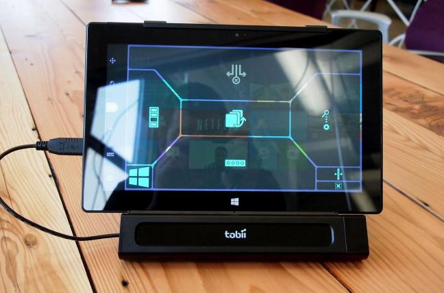
Eye-Phone: Activating Mobile Phones With Your Eyes

images (2)

ABSTRACT:
As smartphones evolve researchers are studying new techniques
to ease the human-mobile interaction. We propose
EyePhone, a novel “hand-free” interfacing system capable of
driving mobile applications/functions using only the user’s
eyes movement and actions (e.g., wink). EyePhone tracks
the user’s eye movement across the phone’s display using the
camera mounted on the front of the phone; more specifically,
machine learning algorithms are used to:

Bionic_Eye-420x0

i) track the eye and
infer its position on the mobile phone display as a user views
a particular application; and

ii) detect eye blinks that emulate
mouse clicks to activate the target application under
view. We present a prototype implementation of EyePhone
on a Nokia N810, which is capable of tracking the position
of the eye on the display, mapping this positions to an application
that is activated by a wink. At no time does the
user have to physically touch the phone display.

  • 1. INTRODUCTION

Human-Computer Interaction (HCI) researchers and phone
vendors are continuously searching for new approaches to

images

reduce the effort users exert when accessing applications on
limited form factor devices such as mobile phones. The most
significant innovation of the past few years is the adoption of
Permission to make digital or hard copies of all or part of this work for
personal or classroom use is granted without fee provided that copies are
not made or distributed for profit or commercial advantage and that copies
bear this notice and the full citation on the first page. To copy otherwise, to
republish, to post on servers or to redistribute to lists, requires prior specific
permission and/or a fee.

Several recent research projects demonstrate new peopleto-
mobile phone interactions technologies. For example, to infer and detect gestures made by the
user, phones use the on-board accelerometer , camera
, specialized headsets , dedicated sensors  or radio
features . We take a different approach than that found
in the literature and propose the EyePhone system which
exploits the eye movement of the user captured using the
phone’s front-facing camera to trigger actions on the phone.
HCI research has made remarkable advances over the last
decade  facilitating the interaction of people with machines.
We believe that human-phone interaction (HPI) extends
the challenges not typically found in HCI research,
more specially related to the phone and how we use it.
We term HPI as developing techniques aimed at advancing
and facilitating the interaction of people with mobile
phones. HPI presents challenges that differ somewhat from
traditional HCI challenges. Most HCI technology addresses
the interaction between people and computers in “ideal”
environments, i.e., where people sit in front of a desktop
machine with specialized sensors and cameras centered on
them. In contrast, mobile phones are mobile computers with
which people interact on the move under varying conditions
and context. Any phone’s sensors, e.g., accelerometer, gyroscope,
or camera, used in a HPI technology must take
into account the constraints that mobility brings into play.
For example, a person walking produces a certain signature
in the accelerometer readings that must be filtered out before
being able to use the accelerometer for gesture recognition
(e.g., double tapping the phone to stop an incoming
phone call). Similarly, if the phone’s camera is adopted in a
HPI application  the different light conditions and
blurred video frames due to mobility make the use of the
camera to infer events very challenging. For these reasons
HCI technologies need to be extended to be applicable to
HPI environments.

download
In order to address these goals HPI technology should be
less intrusive; that is,

i) it should not rely on any external
devices other than the mobile phone itself;

ii) it should be
readily usable with minimum user dependency as possible;
iii) it should be fast in the inference phase;

iv) it should be
lightweight in terms of computation; and

v) it should preserve
the phone user experience, e.g., it should not deplete
the phone battery over normal operations.

Tobii-eye-tracking-step-by-step-web-573

We believe that HPI research advances will produce a leap
forward in the way people use their mobile phones by improving
people safety, e.g., HPI techniques should aim to reduce
the distraction and consequently the risk of accidents if
driving for example, or facilitating the use of mobile phones
for impaired people (e.g., people with disabilities).
We propose EyePhone, the first system capable of tracking
a user’s eye and mapping its current position on the
display to a function/application on the phone using the
phone’s front-facing camera. EyePhone allows the user to
activate an application by simply “blinking at the app”, emulating
a mouse click. While other interfaces could be used
in a hand-free manner, such as voice recognition, we focus
on exploiting the eye as a driver of the HPI. We believe
EyePhone technology is an important alternative to, for example,
voice activation systems based on voice recognition,
since the performance of a voice recognition system tends to
degrade in noisy environments.
The front camera is the only requirement in EyePhone.
Most of the smartphones today are equipped with a front
camera and we expect that many more will be introduced
in the future (e.g., Apple iPhone 4G [1]) in support of video
conferencing on the phone. The EyePhone system uses machine
learning techniques that after detecting the eye create
a template of the open eye and use template matching for
eye tracking. Correlation matching is exploited for eye wink
detection . We implement EyePhone on the Nokia N810
tablet and present experimental results in different settings.
These initial results demonstrate that EyePhone is capable
of driving the mobile phone. An EyePhone demo can be
found at .

  • 2. HUMAN-PHONE INTERACTION

the-eye-mobile-phone-a-great-combination-of-fun-and-functionality2

Human-Phone Interaction represents an extension of the
field of HCI since HPI presents new challenges that need
to be addressed specifically driven by issues of mobility, the
form factor of the phone, and its resource limitations (e.g.,
energy and computation). More specifically, the distinguishing
factors of the mobile phone environment are mobility and
the lack of sophisticated hardware support, i.e., specialized
headsets, overhead cameras, and dedicated sensors, that are
often required to realize HCI applications. In what follows,
we discuss these issues.

Mobility Challenges:

One of the immediate products
of mobility is that a mobile phone is moved around through
unpredicted context, i.e., situations and scenarios that are
hard to see or predict during the design phase of a HPI application.
A mobile phone is subject to uncontrolled movement,
i.e., people interact with their mobile phones while
stationary, on the move, etc. It is almost impossible to predict
how and where people are going to use their mobile
phones. A HPI application should be able to operate reliably
in any encountered condition. Consider the following examples:
two HPI applications, one using the accelerometer, the
other relying on the phone’s camera. Imagine exploiting the
accelerometer to infer some simple gestures a person can perform
with the phone in their hands, e.g., shake the phone
to initiate a phone call, or tap the phone to reject a phone
call [7]. What is challenging is being able to distinguish
between the gesture itself and any other action the person
might be performing.

eyePhone

For example, if a person is running or
if a user tosses their phone down on a sofa, a sudden shake
of the phone could produce signatures that could be easily
confused with a gesture. There are many examples where
a classifier could be easily confused. In response, erroneous
actions could be triggered on the phone. Similarly, if the
phone’s camera is used to infer a user action [5][9], it becomes
important to make the inference algorithm operating
on the video captured by the camera robust against lighting
conditions, which can vary from place to place. In addition,
video frames blur due to the phone movement. Because HPI
application developers cannot assume any optimal operating
conditions (i.e., users operating in some idealized manner)
before detecting gestures in this example, (e.g., requiring a
user to stop walking or running before initiating a phone call
by a shaking movement), then the effects of mobility must
be taken into account in order for the HPI application to be
reliable and scalable.. Any HPI application should
rely as much as possible on just the phone’s on-board sensors.
Although modern smartphones are becoming more computationally
capable [16], they are still limited when running
complex machine learning algorithms [14]. HPI solutions
should adopt lightweight machine learning techniques
to run properly and energy efficiently on mobile phones.

  • 3. EYEPHONE DESIGN

Sony Move Omnivision 101016_move_teardown_5_700

One question we address in this paper is how useful is a
cheap, ubiquitous sensor, such as the camera, in building
HPI applications. We develop eye tracking and blink detection
mechanisms based algorithms  originally designed
for desktop machines using USB cameras. We show
the limitations of an off-the-shelf HCI technique when
used to realize a HPI application on a resource limited mobile
device such as the Nokia N810. The EyePhone algorithmic
design breaks down into the following pipeline phases:
1) an eye detection phase; 2) an open eye template creation
phase; 3) an eye tracking phase; 4) a blink detection phase.
In what follows, we discuss each of the phases in turn.
Eye Detection. By applying a motion analysis technique
which operates on consecutive frames, this phase consists
on finding the contour of the eyes. The eye pair is identified
by the left and right eye contours. While the original
algorithm [17] identifies the eye pair with almost no error
when running on a desktop computer with a fixed camera
(see the left image in Figure 1), we obtain errors when the
algorithm is implemented on the phone due to the quality of
the N810 camera compared to the one on the desktop and
Figure 1: Left figure: example of eye contour pair returned
by the original algorithm running on a desktop
with a USB camera. The two white clusters
identify the eye pair. Right figure: example of number
of contours returned by EyePhone on the Nokia
N810. The smaller dots are erroneously interpreted
as eye contours.

eyePhone-642x423
the unavoidable movement of the phone while in a person’s
hand (refer to the right image in Figure 1). Based on these
experimental observations, we modify the original algorithm
by: i) reducing the image resolution, which according to the
authors in [13] reduces the eye detection error rate, and ii)
adding two more criteria to the original heuristics that filter
out the false eye contours. In particular, we filter out all
the contours for which their width and height in pixels are
such that widthmin ≤ width ≤ widthmax and heightmin ≤ height ≤ heightmax. The widthmin, widthmax, heightmin,
and heightmax thresholds, which identify the possible sizes
for a true eye contour, are determined under various experimental
conditions (e.g., bright, dark, moving, not moving)
and with different people. This design approach boosts the
eye tracking accuracy considerably, as discussed in Section
4.
Open Eye Template Creation. While the authors
in [13] adopt an online open eye template creation by extracting
the template every time the eye pair is lost (this
could happen because of lighting condition changes or movement
in the case of a mobile device), EyePhone does not
rely on the same strategy. The reduced computation speed
compared to a desktop machine and the restricted battery
requirements imposed by the N810 dictate a different approach.
EyePhone creates a template of a user’s open eye
once at the beginning when a person uses the system for
the first time using the eye detection algorithm described
above1. The template is saved in the persistent memory of
the device and fetched when EyePhone is invoked.

Tangible Media Group, MIT, Cambridge, MA USA

By taking
this simple approach, we drastically reduce the runtime
inference delay of EyePhone, the application memory footprint,
and the battery drain. The downside of this off-line
template creation approach is that a template created in certain
lighting conditions might not be perfectly suitable for
other environments. We intend to address this problem as
part of our future work.
In the current implementation the system is trained individually,
i.e., the eye template is created by each user
when the application is used for the first time. In the future,
we will investigate eye template training by relying on
pre-collected data from multiple individuals. With this supervised
learning approach users can readily use EyePhone
without going through the initial eye template creation phase.
Eye Tracking. The eye tracking algorithm is based on
1The eye template is created by putting the phone at a distance
of about 20 cm from the eyes.

smart-phones

The template matching function calculates
a correlation score between the open eye template,
created the first time the application is used, and a search
window. In order to reduce the computation time of the
template matching function and save resources, the search
window is limited to a region which is twice the size of a
box enclosing the eye. These regions are shown in Figure 2,
where the outer box around the left eye encloses the region
where the correlation score is calculated. The correlation coefficient
we rely on, which is often used in template matching
problems, is the normalized correlation coefficient defined in
[18]. This coefficient ranges between -1 and 1. From our
experiments this coefficient guarantees better performance
than the one used in [13]. If the normalized correlation coefficient
equals 0.4 we conclude that there is an eye in the
search window. This threshold has been verified accurate
by means of multiple experiments under different conditions
(e.g., bright, dark, moving, not moving).
Blink Detection. To detect blinks we apply a thresholding
technique for the normalized correlation coefficient
returned by the template matching function as suggested in
[13]. However, our algorithm differs from the one proposed
in [13]. In [13] the authors introduce a single threshold T
and the eye is deemed to be open if the correlation score
is greater than T, and closed vice versa. In the EyePhone
system, we have two situations to deal with: the quality of
the camera is not the same as a good USB camera, and the
phone’s camera is generally closer to the person’s face than
is the case of using a desktop and USB camera. Because of
this latter situation the camera can pick up iris movements,
i.e., the interior of the eye, due to eyeball rotation. In particular,
when the iris is turned towards the corner of the eye,
upwards or downwards, a blink is inferred even if the eye
remains open. This occurs because in this case the majority
of the eye ball surface turns white which is confused with
the color of the skin. We derive four thresholds: Tmin
1 =
0.64, Tmax
1 = 0.75, Tmin
2 = -0.53, and Tmax
2 = -0.45. These
Table 1: EyePhone average eye tracking accuracy
for different positions of the eye in different lighting
and movement conditions and blink detection average
accuracy. Legend: DS = eye tracking accuracy
measured in daylight exposure and being steady; AS
= eye tracking accuracy measured in artificial light
exposure and being steady; DM = eye tracking accuracy
measured in daylight exposure and walking;
BD = blink detection accuracy in daylight exposure.
Eye position DS AS DM BD
Top left 76.73% 74.50% 82.81% 84.14%
Top center 79.74% 97.78% 79.16% 78.47%
Top right 80.35% 95.06% 60% 82.17%
Middle left 98.46% 97.19% 70.99% 74.72%
Middle center 99.31% 84.09% 76.52% 79.55%
Middle right 99.42% 75.79% 65.15% 80.1%
Bottom left 98.36% 93.22% 78.83% 74.53%
Bottom center 90.76% 71.46% 85.26% 67.41%
Bottom right 84.91% 93.56% 78.25% 72.89%
thresholds are determined experimentally and again under
different experimental conditions as discussed previously. If
we indicate with cmin and cmax, respectively, the minimum
and maximum normalized correlation coefficient values returned
by the template matching function, the eye is inferred
to be closed if Tmin.eye-phone

  • 4. EVALUATION

In this section, we discuss initial results from the evaluation
of the EyePhone prototype. We implement EyePhone
on the Nokia N810 [19]. The N810 is equipped with a 400
MHz processor and 128 MB of RAM2. The N810 operating
system is Maemo 4.1, a Unix based platform on which
we can install both the C OpenCV (Open Source Computer
Vision) library [20] and our EyePhone algorithms which are
cross compiled on the Maemo scratchbox. To intercept the
video frames from the camera we rely on GStreamer [21], the
main multimedia framework on Maemo platforms. In what
follows, we first present results relating to average accuracy
for eye tracking and blink detection for different lighting and
user movement conditions to show the performance of Eye-
Phone under different experimental conditions. We also report
system measurements, such as CPU and memory usage,
battery consumption and computation time when running
EyePhone on the N810. All experiments are repeated five
times and average results are shown.
Daylight Exposure Analysis for a Stationary Subject.
The first experiment shows the performance of Eye-
Phone when the person is exposed to bright daylight, i.e., in
a bright environment, and the person is stationary. The eye
tracking results are shown in Figure 2. The inner white box
in each picture, which is a frame taken from the front camera
when the person is looking at the N810 display while hold-
2The reason we use the N810 instead of the Nokia N900
smartphone is because we obtain better quality video frames
from the front camera. However, with its 600 MHz processor
and up to 1 GB of application memory the N900 presents a
more powerful hardware than the N810. Hence, we expect
better performance (computation and inference delay) when
running EyePhone on the N900. This is part of our on-going
work.
1375677750_533984938_3-Samsung-Galaxy-S4-Eye-Motion-Sensor-Vietnam-Karachi
ing the device in their hand, represents the eye position on
the phone display. It is evident that nine different positions
for the eye are identified. These nine positions of the eye
can be mapped to nine different functions and applications
as shown in Figure 4. Once the eye locks onto a position
(i.e., the person is looking at one of the nine buttons on the
display), a blink, acting as a mouse click, launches the application
corresponding to the button. The accuracy of the
eye tracking and blink detection algorithms are reported in.

Artificial Light Exposure for a Stationary Subject.
In this experiment, the person is again not moving but in
an artificially lit environment (i.e., a room with very low
daylight penetration from the windows). We want to verify
if different lighting conditions impact the system’s performance.
The results, shown in Table 1, are comparable to
the daylight scenario in a number of cases. However, the
accuracy drops. Given the poorer lighting conditions, the
eye tracking algorithm fails to locate the eyes with higher
frequency.
Daylight Exposure for Person Walking. We carried
out an experiment where a person walks outdoors in a bright
environment to quantify the impact of the phone’s natural
movement; that is, shaking of the phone in the hand induced
by the person’s gait. We anticipate a drop in the accuracy of
the eye tracking algorithm because of the phone movement.
This is confirmed by the results shown in Table 1, column
4. Further research is required to make the eye tracking
algorithm more robust when a person is using the system
on the move.
Impact of Distance Between Eye and Tablet. Since
in the current implementation the open eye template is created
once at a fixed distance, we evaluate the eye tracking
performance when the distance between the eye and the
tablet is varied while using EyePhone. We carry out the
measurements for the middle-center position in the display
(similar results are obtained for the remaining eight positions)
when the person is steady and walking. The results
Table 2: Average CPU usage, RAM usage, and computation
time for one video frame. The front camera
supports up to 15 frames per second. The last
column reports the percentage of used battery by
EyePhone after a three hour run of the system.
CPU RAM Computation time Battery used after 3h
65.4% 56.51% ∼100 msec 40%
are shown in Figure 3. As expected, the accuracy degrades
for distances larger than 18-20 cm (which is the distance between
the eye and the N810 we currently use during the eye
template training phase). The accuracy drop becomes severe
when the distance is made larger (e.g., ∼45 cm). These
results indicate that research is needed in order to design
eye template training techniques which are robust against
distance variations between the eyes and the phone.
System Measurements. In Table 2 we report the average
CPU usage, RAM usage, battery consumption, and
computation time of the EyePhone system when processing
one video frame – the N810 camera is able to produce up
to 15 frames per second. EyePhone is quite lightweight in
terms of CPU and RAM needs. The computation takes 100
msec/frame, which is the delay between two consecutive inference
results. In addition, the EyePhone runs only when
the eye pair is detected implying that the phone resources
are used only when a person is looking at the phone’s display
and remain free otherwise. The battery drain of the N810
when running the EyePhone continuously for three hours is
shown in the 4th column of Table 2. Although this is not
a realistic use case, since a person does not usually continuously
interact with their phone for three continuous hours,
the result indicates that the EyePhone algorithms need to
be further optimized to extend the battery life as much as
possible.

  • 4.1 Applications

images (1)

EyeMenu. An example of an EyePhone application is
EyeMenu as shown in Figure 4. EyeMenu is a way to shortcut
the access to some of the phone’s functions.

ku-xlarge

The set
of applications in the menu can be customized by the user.
The idea is the following: the position of a person’s eye is
mapped to one of the nine buttons. A button is highlighted
when EyePhone detects the eye in the position mapped to
the button. If a user blinks their eye, the application associated
with the button is lunched. Driving the mobile phone
user interface with the eyes can be used as a way to facilitate
the interaction with mobile phones or in support of people
with disabilities.

best-iPhone-apps-coaches-eye
Car Driver Safety. EyePhone could also be used to
detect drivers drowsiness and distraction in cars. While car
manufactures are developing technology to improve drivers
safety by detecting drowsiness and distraction using dedicated
sensors and cameras [22], EyePhone could be readily
usable for the same purpose even on low-end cars by just
clipping the phone on the car dashboard.

  • 5. FUTURE WORK

the-eye-mobile-phone-a-great-combination-of-fun-and-functionality3

We are currently working on improving the creation of the
open eye template and the filtering algorithm for wrong eye
contours. The open eye template quality affects the accuracy
of the eye tracking and blink detection algorithms. In
particular, variations of lighting conditions or movement of
the phone in a person’s hand might make the one-time template
inaccurate by not matching the current conditions of
the user. A template created in a bright environment might
work poorly to match the eye in a darker setting. Similarly,
an eye template created when the person is stationary does
not match the eye when the person is walking. We observe
the implications of the one-time template strategy in the results
presented.Future-smartphones-h

. It is important to modify the
template generation policy in order for the system to be able
to either evolve the template according to the encountered
contexts if the template is generated in a context different
from the current one, or, create new templates on the fly for
each of the encountered settings (e.g., bright, dark, moving,
etc.). In both cases the template routine should be fast to
compute and minimize the resources used.
A second important issue that we are working on is a filtering
algorithm that minimizes false positives, (i.e., false eye
contours). One way to solve this problem is by using a learning
approach instead of a fixed thresholding policy. With a
learning strategy the system could adapt the filter over time
according to the context it operates in. For example, a semisupervised
learning approach could be adopted, having the
system evolve by itself according to a re-calibration process
every time a completely new environment is encountered. In
order to be sure the filter is evolving in the right direction
the user could be brought into the loop by asking if the result
of the inference is correct. If so, the new filter parameters
are accepted, otherwise, discarded. Clearly, proper and effective
user involvement policies are required, so prompting
is not annoying to the user.

  • 6. RELATED WORK

Tobii-EyeMobile-Eye-Control-front-menu

There are a number of developments in HCI related to
mobile phones over the last several years. Some of this work exploits accelerometers on the phone
in order to infer gestures. The PhonePoint Pen project [4]
is the first example of a phone being transformed into a
pen to write in the air in order to quickly take small notes
without needing to either write on paper or type on a computer.
A similar project evaluated on the iPhone has recently
been proposed [8]. The uWave project [7] exploits a
3-D accelerometer on a Wii remote-based prototype for personalized
gesture recognition. Phones can be used as radars
as in [10] where proximity based sensing is used to infer
speed of surrounding subjects.
Custom-built sensors interfaced with a mobile phone are
used for driving the phone user interface by picking up eye
movement [6] or converting muscular movement into speech
[9]. The drawback of these technologies is that they require
the support of external sensors attached to the mobile phone
which might be an obstacle towards the large scale adoption
of the technology.
Eye movement has recently been used for activity recognition
[24]. By tracking the eye researchers show that it is
possible to infer the actions of watching a video, browsing
the web or reading notes.
The work in [5, 23, 11, 13] is more closely related to the
EyePhone system. The eyeSight [5] technology exploits the
phone camera to control the mobile phone by simple hand
gestures over the camera. The openEye project [23] relies
on an eyeglasses mounted camera to track a person’s eyes to
realize HCI applications. The Eye Mouse project [11] and
[13] are designed for desktop machines with fixed cameras
pointed at the user to pick up eye movement and use the
eye as a mouse in [11], or to enable general HCI applications
[13]. However, these systems are for static machines, using
a specific fixed infrastructure of external sensors and cannot
be easily replicated on mobile phones.

  • 7. CONCLUSION

In this paper, we have focused on developing a HPI technology
solely using one of the phone’s growing number of onboard
sensors, i.e., the front-facing camera. We presented
the implementation and evaluation of the EyePhone prototype.
The EyePhone relies on eye tracking and blink detection
to drive a mobile phone user interface and activate
different applications or functions on the phone. Although
preliminary, our results indicate that EyePhone is a promising
approach to driving mobile applications in a hand-free
manner. A video of the EyePhone demo can be found at

images (3)

  • 8. ACKNOWLEDGMENTS

This work is supported in part by Nokia, Intel Corp.,
Microsoft Research, NSF NCS-0631289, and the Institute
for Security Technology Studies (ISTS) at Dartmouth College.
ISTS support is provided by the U.S. Department of
Homeland Security under award 2006-CS-001-000001, and
by award 60NANB6D6130 from the U.S. Department of
Commerce. The views and conclusions contained in this
document are those of the authors and should not be interpreted
as necessarily representing the official policies, either
expressed or implied, of any funding body.
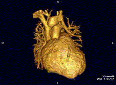